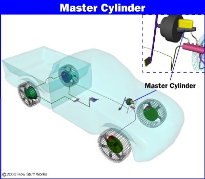
Modern vehicles don’t rely on a single, fragile line of hydraulic fluid to stop you. They use a split design. Two independent circuits control the braking power, typically splitting the load between two wheels each. If one line bursts, the other half of the system still works. You lose half your stopping power, sure, but you aren’t just sliding into a wall with zero friction.
The heart of this dual-circuit safety net is the master cylinder. It’s a clever bit of engineering packed with two pistons inside one body. This setup ensures that even if one piston seal fails, the other can often still generate enough pressure to keep the car manageable. Sitting right next to it is the combination valve. This unsung hero monitors pressure differences between the circuits. If something goes wrong—like a leak in one circuit—it triggers a warning light for the driver. It also handles biasing to keep the front and rear brakes balanced under heavy load.
We are going to look under the hood at exactly how these two components interact to keep you from becoming a crumple zone. If you are rusty on the basics of how pads, rotors, and fluid pressure translate into physical friction, you should probably read a primer on basic brake mechanics first. For now, let’s zoom in on the master cylinder.
Locating the Master Cylinder
You won’t find the master cylinder in the trunk or near the wheels. It lives up front, mounted directly on the power brake booster. This booster is bolted to the firewall, the metal wall separating the engine bay from the passenger cabin.
The booster itself is a vacuum-assisted device. It uses the engine’s intake manifold vacuum to multiply the force you apply to the brake pedal. So, when you press the pedal, you aren’t just pushing fluid; you’re triggering a vacuum system that amplifies your leg strength before that force reaches the master cylinder.
The master cylinder itself is usually a cast aluminum or iron block. It connects to the brake fluid reservoir on top via rubber seals and hoses. This reservoir holds the extra brake fluid needed to fill the lines as the brake pads wear down and the pistons extend further into their calipers. As the pads wear, the fluid level doesn’t drop significantly because the caliper pistons simply move out to take up the slack.
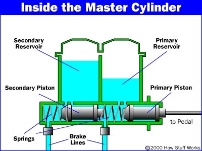
Inside the master cylinder, you have two primary pistons arranged in tandem. They share a common pushrod connected to the brake booster. When you hit the brakes, the pushrod drives both pistons forward. The first piston pressurizes the primary circuit. The second piston, located behind the first, pressurizes the secondary circuit. Because they are connected, they move together, but they can operate somewhat independently if one seal leaks.
The Role of the Combination Valve
The combination valve is a compact unit, often integrated into the master cylinder body or mounted nearby in the engine bay. Its job is passive but critical. It monitors the hydraulic pressure in both circuits.
If a leak develops in one circuit, the pressure in that line drops. The valve detects this imbalance. It doesn’t just sit there; it physically shifts to isolate the leaking circuit as much as possible, trying to maintain pressure in the good circuit. Simultaneously, it triggers a pressure differential switch. This switch closes an electrical circuit that
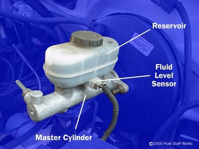
The master cylinder sits directly against the firewall, bolted to the brake booster on the driver’s side. It’s the component that turns your foot pressure into hydraulic force. Most drivers never see it, but you can find it by following the brake lines from the pedal back into the engine bay.
Identifying the Reservoir and Sensor
Look for the translucent plastic tank mounted on top of the unit. This is the brake-fluid reservoir. It holds the brake fluid that feeds the master cylinder. The fluid level drops as the brake pads wear, so the tank is designed to hold enough reserve to keep the system full.
Attached to the side of the reservoir is an electrical connector. This is a fluid level sensor. It’s a simple switch that grounds the circuit when the fluid drops below a safe mark. When that happens, the red brake warning light on your dashboard illuminates. It’s not an ABS fault. It’s a direct signal that you need to top off the fluid.
Why Location Matters
Knowing where this is helps with maintenance. You don’t need to bleed the entire system just to add fluid. But if the sensor triggers early, it might mean leaks elsewhere. Check the calipers, wheel cylinders, and brake hoses. The reservoir doesn’t lose fluid on its own. It’s a closed loop.
The sensor is a basic float switch. Low fluid = low resistance = warning light.
If you’re under the hood, trace the lines. They’re usually steel or rubber, leading from the master cylinder to each corner. The reservoir is the starting point. Keep it clean. Dirt in the fluid kills master cylinders.
How a Dual-Circuit Master Cylinder Handles Failure
The master cylinder isn’t just a simple pump. Inside that aluminum or plastic housing, you have two separate pistons, two springs, and two distinct fluid chambers. They work in tandem, but they are designed to survive each other’s failure.
Here is the sequence when you stomp on the brake pedal. The linkage pushes the primary piston forward. Fluid pressure builds in the first circuit. As that pressure rises, it pushes against the back of the secondary piston. This secondary piston then compresses the fluid in the second circuit. In a healthy system, pressure equalizes. Both circuits see the same force. You get balanced braking.
But systems leak.
If a caliper bleeds dry or a rear wheel cylinder cracks open, that specific circuit loses pressure. The master cylinder reacts in a specific mechanical way. The pressure wave that usually pushes the secondary piston forward vanishes. Without that opposing force, the primary piston slams into the secondary piston. They lock together.
The master cylinder effectively becomes a single-piston device.
This is a fail-safe feature, not a design flaw. The second circuit remains pressurized. It works. But you have to press the brake pedal significantly further down the travel to engage it. The pedal feels soft or spongy because you are filling the void left by the leak before pressure can actually build.
The result is poor braking. With only two wheels (usually the front wheels on most front-wheel-drive setups) providing stopping power, your deceleration drops drastically. You will feel the car pull to one side if the leak is on the opposite diagonal, or just stop less effectively overall. Do not drive like this.
The Role of the Combination Valve
Most vehicles with front disc brakes and rear drum brakes include a combination valve. This is a single unit that houses multiple functions, usually mounted on the brake line or near the master cylinder.
Why is it there? Because discs and drums behave differently. Discs need less fluid volume to engage but generate more heat. Drums require more fluid volume to expand the shoes against the drum. The combination valve manages this disparity.
It typically contains three components in one housing:
- Pressure Differential Switch: This is the electrical sensor that triggers the brake warning light on your dash. If pressure drops between the two circuits (like in the leak scenario above), the switch closes the circuit to ground, lighting up that red brake light. It tells you the system is compromised.
- Proportioning Valve: This restricts fluid pressure to the rear drum brakes. Without it, the rear drums would lock up before the front discs even bite, especially under hard braking. It ensures the front brakes do the heavy lifting while keeping the rear wheels rotating just enough for stability.
- Metering Valve: This holds back pressure to the rear brakes for a split second during initial pedal application. It allows the front disc calipers to close up the gap between pads and rotors before the rear drum shoes expand. This synchronizes the brake application so you don’t get a jerky, uneven stop.
You won’t find this on every car. Pure disc-brake systems often use an ABS module to handle pressure modulation. But if you are working on an older sedan or a truck with rear drums, this valve is the brain of the hydraulic balance.
The Combo Valve: One Part, Three Jobs
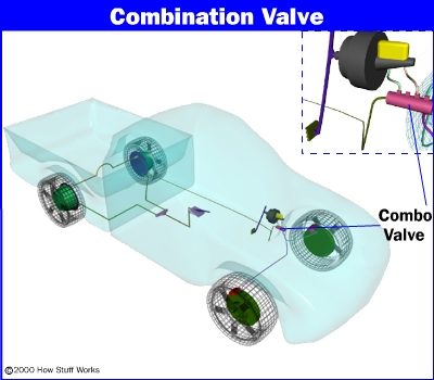
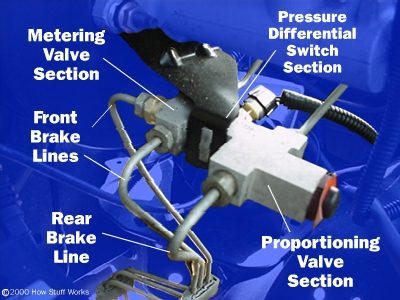
Locating the combination valve is the first step, but understanding why it exists is what actually helps you fix the brake system. You won’t find separate canisters for metering, pressure differential switching, or proportioning. In most modern passenger cars and light trucks, these three distinct functions are squished into a single unit. This is the combination valve.
It sits in the brake line, usually mounted to the firewall or the frame rail. Its job is to manage hydraulic pressure distribution and alert you when something is wrong. If you’re hunting for it, look between the master cylinder and the front/rear split. It’s the metal block with two or three fittings entering and exiting.
Breaking Down the Trio
The unit does the work of three separate devices. Here is what each part of the combo valve actually controls.
The Metering Valve
This component holds back front brake pressure until the rear brakes are engaged. Without it, your front discs would lock up before the rear drums (or discs) even started squeezing. The metering valve delays front pressure by about 0.1 to 0.2 seconds. This ensures both front and rear brakes apply at the same time. It stays closed until pressure builds to a set point, usually around 100 to 150 psi. Once that threshold is hit, the valve opens and lets pressure flow to the front.
The Proportioning Valve
This is the pressure reducer. Rear brakes don’t need as much hydraulic force as the fronts, especially under heavy braking when weight transfers forward. If you sent 100% of the master cylinder pressure to the rear wheels, they would lock up instantly. The proportioning valve caps the rear pressure. In a typical setup, it might limit rear pressure to 60% or 70% of the front pressure. This keeps the rear tires near the threshold of slip without actually locking them. Some older cars have a separate metering and proportioning valve. Modern cars combine them into one unit for space and cost savings.
The Pressure Differential Switch
This is the electrical brain of the combo valve. Inside the housing, a piston moves based on hydraulic pressure balance. If there’s a leak in one circuit—say, a soft rear brake line—the piston shifts off-center. This movement triggers an electrical switch. The switch completes a circuit to ground, turning on the brake warning light on your dash. It’s a simple but effective safety check. If the light comes on, you have a pressure imbalance. Don’t ignore it.
Why Location Matters
The combination valve is typically mounted on the driver’s side firewall, near the brake master cylinder. In some vehicles, it’s bolted to the frame rail near the wheel well. The exact location varies by make and model. If you’re replacing it, you’ll need to disconnect the brake lines. Have rags and a catch tank ready. Brake fluid eats paint. It also corrodes metal parts if left sitting.
When you remove the combo valve, inspect the mounting bolts for corrosion. Rust can seize these bolts, making removal a nightmare. Penetrating oil helps, but sometimes heat is needed. Use caution near brake lines and hoses. Heat can damage rubber components.
Symptoms of a Failing Combo Valve
A bad combination valve often shows up in two ways. First,
Why Your Rear Brakes Need a Head Start
The combination valve isn’t just one part. It’s a cluster of functions housed in a single unit, and three of those sections do distinct jobs. First, there’s the metering valve. This component is mandatory for any vehicle mixing front disc brakes and rear drum brakes.
Disc brake pads sit flush against the rotor. Drum brake shoes hang loose, away from the drum surface. Push the pedal. The discs grab instantly. The drums lag behind. Without intervention, the front brakes bite first. This causes instability. The car wants to dive or skid.
The metering valve fixes this timing gap. It blocks hydraulic pressure to the front discs entirely. It waits. It holds back. Only when system pressure hits a specific threshold does the valve open. That threshold is low. It’s just enough to push the drum shoes outward until they kiss the drum.
Result? The rear brakes engage a fraction of a second before the fronts. This slight delay keeps the chassis square. It acts like a rudder on an airplane. The car tracks straight. You stop with control, not a spin.
The Leak Detector in Your Valve Block
Next comes the pressure differential switch. This is your early warning system for hydraulic failure. Inside the valve, a small piston floats in a cylinder. The left side connects to one brake circuit. The right side to the other.
Under normal conditions, pressure balances the piston. It stays dead center. But what if a line bursts? Or a caliper leaks? Pressure drops on that side. The piston shifts. It tilts off-center.
This movement closes an electrical switch. The wires leading to this mechanism are visible in standard diagrams. The switch triggers the red brake warning light on your dashboard. You know immediately that one circuit has failed. The other circuit still works, but you have no redundancy. You drive to a mechanic. You do not drive across the state.
Managing Weight Transfer with Proportioning
The third section is the proportioning valve. Its job is simple. It reduces hydraulic pressure sent to the rear brakes.
Why? Weight transfer. When you brake, inertia throws the car’s weight forward. The nose dips. The rear lifts. Less weight on the rear tires means less traction. If you applied equal pressure to all four wheels, the rears would lock up instantly. Locked wheels mean no steering and longer stopping distances.
Most cars are front-heavy anyway. The engine sits up front. This adds even more downward force on the front axle. The front brakes need more clamping force to match this weight. The rear brakes need less.
The proportioning valve restricts flow. It limits rear pressure to a safe percentage. If the valve is set to 70%, and your master cylinder pushes 1,000 psi to the front, the rear only sees 700 psi. The fronts handle the bulk of the stopping power. The rears hold the line without skidding.
It’s a delicate balance. Too little rear pressure, and you waste potential stopping power. Too much, and you fishtail into a ditch. The valve sits in the middle. It works silently. Until you slam the brakes. Then you feel exactly why it’s there.
Related HowStuffWorks Articles
-
How Anti-Lock Brakes Work
-
How Brakes Work
-
How Disc Brakes Work
-
How Drum Brakes Work
-
How Power Brakes Work
More Great Links
-
Halting History: Brakes Then and Now
-
InnerAuto: Braking System
-
Automotive 101: Brake System Operation – note the DOT brake fluid differences
-
Hydraulic Brakes
-
Master Cylinder Drawings
-
Rebuilding the Brake Master Cylinder
-
Professional Mechanics Online: Brakes
-
Auto.com: Daily automotive news and reviews